Project study / 02
Atlas. See the connections come together.
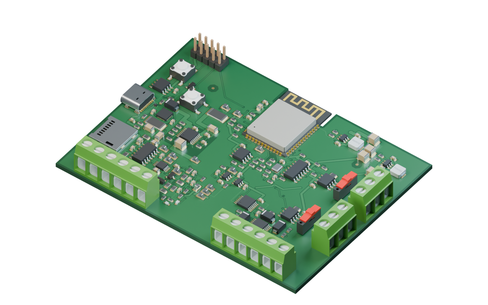
Atlas Control Hub is a PCB Studio project with a denser mix of connectors, modules and supporting electronics. Its assembly study makes that arrangement easier to examine, one stage at a time.
- Board outline
- 100 × 75 mm
- Board thickness
- 1.6 mm
- Models in this study
- 187
A compact board with many interfaces
The published Atlas snapshot fits 187 component models on a 100 × 75 mm board. The visible arrangement includes terminal blocks around the perimeter, a USB-C connection, a module with a printed antenna and groups of smaller supporting components. Together, they create a different inspection problem from OrbitX’s display and tactile controls.
On a board with this many parts, a single final image can hide the relationship between components. The assembly stages give you a way to see the underlying board, add the main groups and then consider how the connections occupy the remaining space.
Three stages, one physical arrangement
The foundations, The intelligence and The connections are the three chapters of the Atlas assembly. Scroll to move through the sequence or select a chapter to revisit it. The board and component models come from the Atlas Control Hub project, with the scene prepared for inspection on the website.
The 187-model counter describes the contents of this assembly snapshot. It is not a fabrication yield, an electrical-check result or a count of independently verified parts. The animation shows where the models are placed, while engineering review determines whether those choices are correct.
Explore the interactive Atlas assemblyInspect the edges as well as the center
A mechanical view is particularly useful for noticing orientation or seating problems. It is one part of review: model dimensions and transforms still need to agree with the physical part, its footprint and the design’s constraints.
- Follow the terminal blocks around the board edge and consider how their access directions relate to the layout.
- Look at the USB-C connector and other interface parts in relation to the board surface.
- Compare the large module with the smaller components around it.
- Use the visible copper, pads and tracks to understand the surface arrangement alongside the 3D models.
Why the board surface is part of the story
Tracks and filled copper areas add context that a plain green board cannot provide. They help you relate the component arrangement to the surface layout and make the assembly more informative when viewed from different angles.
The web scene shows a project snapshot. A visible copper area is not evidence that connectivity, current capacity, clearances or interference have been validated. Use the layout data and the applicable engineering checks when answering those questions.
Shared while it is being developed
Atlas appears alongside Gaming Keyboard and OrbitX in the published montage of native PCB Studio recordings. The montage is edited, and all three projects are still in progress. The Atlas study is not presented as a finished product or a production-approved reference design.
For another perspective on the same workspace, explore OrbitX’s two-sided arrangement and its display, rotary control and keys. Both studies connect the abstract design process to something you can inspect, while keeping the remaining work visible.
Explore OrbitX next