Project study / 01
OrbitX. An idea you can turn over.
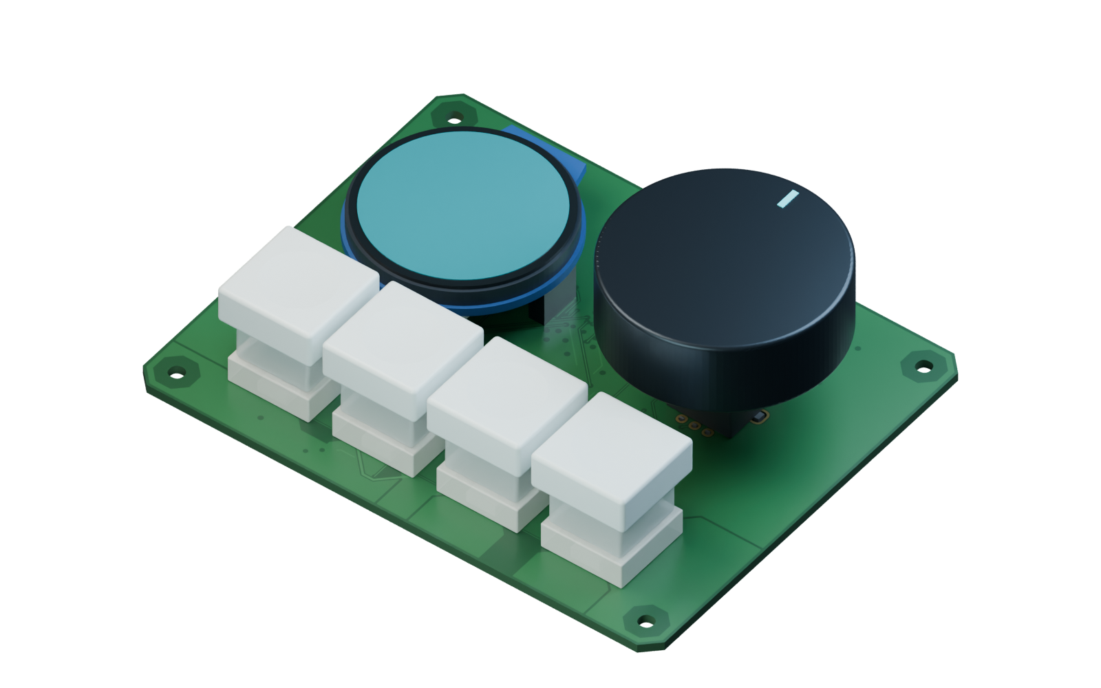
A USB-C desktop controller with a round display, a rotary control and four keys. OrbitX is a real PCB Studio project, shown here as an evolving design and a 3D assembly study.
- Board outline
- 100 × 80 mm
- Board thickness
- 1.6 mm
- Models in this study
- 80
A small controller with a physical interface
OrbitX brings a display and a set of tactile controls onto one desktop board. The round display, rotary control and four keys make the top face easy to read as a physical object. The USB-C connection and supporting electronics bring a second set of placement decisions into the project.
The assembly shown here uses the project’s 100 × 80 mm board outline and 80 component models. These figures describe this published snapshot. They do not indicate a completed electrical design, a manufactured prototype or a validated enclosure.
The underside matters as much as the controls
The interactive sequence begins with the board, adds the underside electronics, then turns to the connections and controls on top. That change of viewpoint makes the relationship between the two faces visible. A part that seems unobtrusive from above can occupy meaningful space beneath the board.
Use the five chapters to move through the same arrangement: The board, The underside, The connection, The controls and OrbitX. You can return to an earlier stage to compare the board before and after a group of components appears. The control does not modify the source project.
Explore the interactive OrbitX assemblyWhat to look for in the 3D view
The rendered copper helps you read the board’s surface. It does not establish electrical connectivity, clearance compliance or signal quality on its own. For those questions, examine the underlying layout and the relevant checks.
- How the display, rotary control and four keys share the available top surface.
- How the USB-C connection relates to the board edge and the controls.
- Which parts occupy the bottom face and how they sit against the board.
- Where visible tracks, pads and filled copper areas meet the component layout.
From an empty project to a closer look
The accompanying native-app walkthrough shows five moments: a new project, describing the idea, following ADE at work, exploring the 3D layout and turning the board over. It is a 20-second edit of actual app recordings, with timing condensed for the demonstration.
The recording and the interactive assembly serve different purposes. The recording shows the workspace in use. The assembly gives you a way to inspect the component arrangement without operating the app. Neither demonstrates that the full design was created or verified in twenty seconds.
What is still open
OrbitX is a work in progress. Component geometry, routing and production readiness still require review. Some parts use simplified or provisional geometry, so their appearance should not be treated as a guaranteed fit for a physical part.
The project is shared to make the development process tangible. If you want to try a similar board in PCB Studio, describe your own requirements in the early-access request. Access is free, reviewed personally and independent of donations.